K 75 Rear Master Brake Cylinder Rebuild
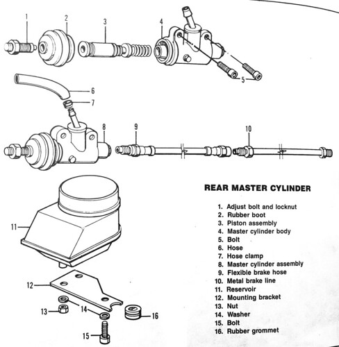
In this article, I will describe replacing the internal assembly within the master cylinder body of my 1995 K 75. I can only assume that this procedure will work with similar non-ABS K 75 models with rear disc brakes. Please refer to the following public-domain schematic of the rear master cylinder as I will be using terminology from it to avoid confusion.
After noticing brake fluid leakage within the rubber boot, I concluded that leakage was likely occurring around two rubber seals in the piston assembly, so I weighed my options. I could purchase and replace the entire cylinder (approximately $350 new) or purchase a rebuild kit and reuse the cylinder body, which would only cost $95.
I opted for the rebuild to keep costs down and ordered and received the kit, part # 34 31 2 311 064. I chose to reuse both the hose that feeds the fluid into the cylinder as well as the flexible brake hose to the rear caliper brake assembly. While the Clymer’s manual is a good guide, there were several details or shortcuts I learned that are absent from the manual’s procedure. An assistant and I completed this in approximately two hours and neither of us is a mechanic, so the repair can certainly be done by almost anyone who has the tools. I will not describe the exact tools needed, but metric Allen wrenches, rubber tubing, open-ended box wrenches, DOT 4 brake fluid, rags, and a bungee cord sufficed for me.
The procedure:
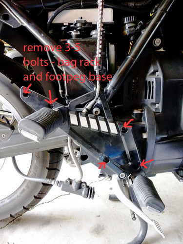
- Remove three bolts holding the right foot peg base to access the cylinder body. If your machine has a bag rack attached (mine does), remove the additional two bolts. Do not dangle the detached foot peg base, as it will strain the brake hoses. Attach a bungee cord to suspend the removed foot peg base. Note: Ensure that the small spring attached to the foot pedal is accounted for and/or removed for later reattachment; this is not depicted in the manuals I consulted.
- Remove two bolts attaching the cylinder body and carefully let it dangle.
- Remove rubber boot from cylinder body
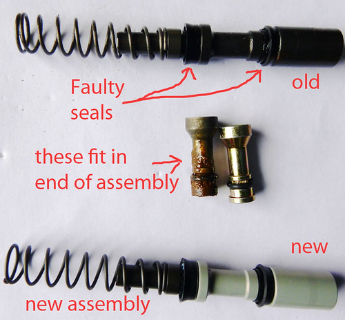
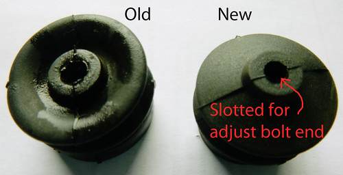
- Unscrew a small retaining screw on the side of the cylinder body, which will permit you to withdraw the piston assembly from the body. This assembly is the part, along with the rubber boot, that you will replace. Examine and lay out the parts in order for reference. In the following photo, the two parts that fit in the end of the assembly are called stoppers and make contact with the adjustment bolt (also see the schematic, above).
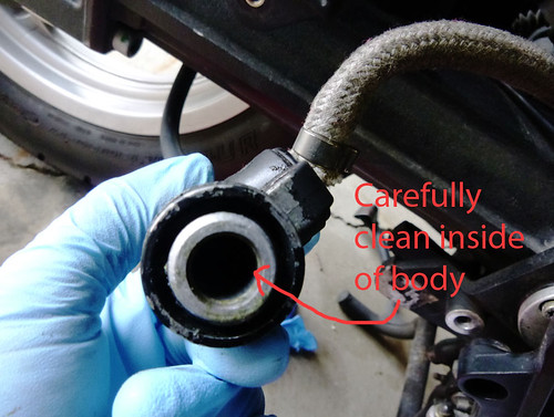
- Clean and flush the inside of the cylinder body to remove any contaminants and coat with brake fluid. Also, soak the new assembly in brake fluid to lubricate and soften seals for later insertion.
- Insert the new piston assembly into the cylinder body, being careful not to distort one of the seals that is cup-shaped. The spring will require you to keep pressure on the assembly until you next screw in the retaining screw into the body, thus holding the assembly within the body. Note: The retaining screw fits between the two seals in the assembly, permitting movement while preventing the assembly from springing out of the body. Check that the assembly compresses and returns smoothly.
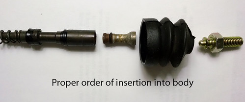
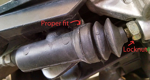
- You may now replace the adjust bolt and locknut (far right in above photo) to the foot brake lever, which first requires loosening a small Allen nut in the brake lever. I did not opt to do this to save time. I inspected the original adjust bolt and it appeared to be in acceptable condition. I didn’t remove it.
- Reattach cylinder body to motorcycle with two bolts.
- Replace rubber boot with new one. This may require some dexterity and patience. Note: The rubber boot has a slot within the opening into which the adjust bolt’s flared end fits. This is not depicted in any manual I consulted.
- Reattach spring on brake lever if necessary and depress lever to test free movement of compression and return of cylinder assembly. At this point mine was frozen and some misalignment between the stopper and adjust bolt was the cause. I removed the retaining spring and worked the movement and it realigned properly. I screwed the retaining screw down and the assembly now moved freely under the spring compression normally.
- Visually inspect and reattach the foot peg base with three bolts and the two bolts for the bag frame if your motorcycle has the frame.
- Bleed and then replace the brake fluid in the system with fresh DOT 4 fluid.
- Test ride machine. At this point you may want to make any adjustment to the feel of the brake lever by loosening the locknut on the adjust bolt and moving it in or out, thus decreasing or increasing the “throw” or movement of the lever. I slightly shortened the throw.
From below, the rear master brake cylinder reattached and rebuild completed:
Anyone wishing to rebuild their own master cylinder may consider replacing the brake hoses as well as a preventative measure. My machine has 27,000 miles on it and is 22 years old. I may replace the hoses in the future. Also, do your best to avoid brake fluid contact with painted surfaces; I took my machine to the car wash and with soap, low-pressure cleaned some areas below the brake reservoir. My thanks to my assistant, Ted. Good luck to all my fellow riders keeping their K 75 motorcycles properly maintained and on the road.