K 75 Final Drive Spline Lube Cradle
I rode my 1990 K 75 from the San Francisco Bay area up to central Oregon in the summer of 2013. The miles melted away in rapid succession, whether on the back roads or the interstate. The smooth and reliable power plant of this machine is legendary.
Those miles add up so quickly that it is easy to go beyond the 10K interval often recommended for servicing the final drive splines on a high-mileage K 75. When I bought my K 75 in 2009, the seller put me at ease by telling me the bike had a recent spline lube; the real question was what condition those splines were in. To answer that question, there is no substitute for disassembly and visual inspection.
After owning my K 75 for a few months I brought it to a trusted mechanic for a rear spline lube just in case the seller wasn’t altogether honest with me. After removing the final drive, the mechanic showed me the compromised condition of the splines, which are supposed to have sharp rectangular edges on each individual spline. Mine were showing unmistakable signs of wear, rounding of the edges. This news put me in a downhearted state as I really wanted my K 75 to be ready for the long haul with few worries. Many of us seek unlimited years and miles of riding ahead when we choose a BMW.
I replaced my final drive and drive shaft with units having new or like-new splines. I then decided to build a device to keep me on track with rear spline maintenance, and get the most miles possible on my replacements. The rear end of the drive shaft has the output splines, while the final drive has the input splines. This pair is what I am focusing on. At the front of the drive shaft and between clutch and transmission are other important splines, but the critical maintenance of those are not being covered in this piece.
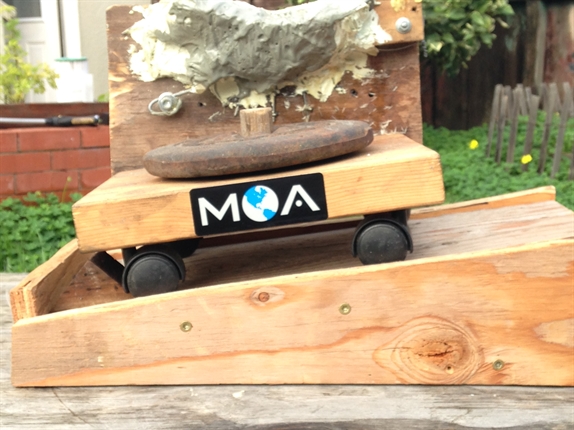
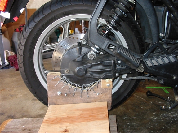
The tool I built can be described as a final drive stand, or a jig, a cradle, and a dolly. It is an aid in all three steps of servicing the rear splines of a monolever K bike like mine.
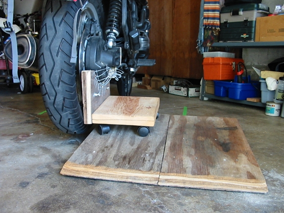
Step 1: Remove final drive from drive shaft
Rear wheel has already been removed, brake calipers secured, and rear portion of speedometer cable disconnected and secured.
The stand/cradle attaches to the final drive with two plastic 12-inch zip ties before removal. After the shock absorber is unbolted, the four Allen bolts connecting the final drive to the drive shaft are removed. The stand, with the final drive mounted upright, is then rolled down the ramp which has the same slope as the drive shaft in its running position. The stand in no way replaces the need to prop up or strap the drive shaft in position before disassembly.
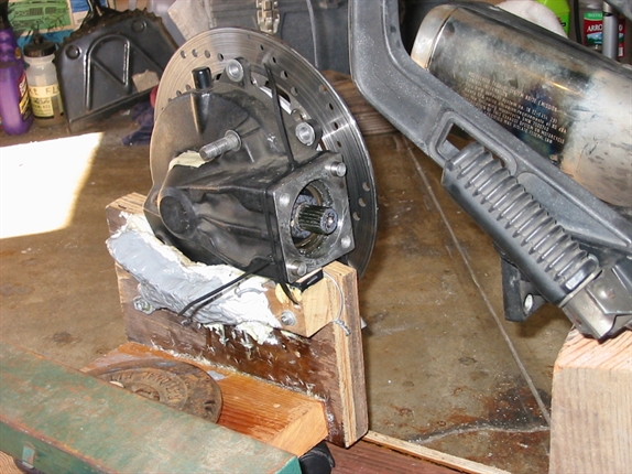
Step 2: Cleaning, inspection, and lubing the splines themselves
This is the most important step. With the final drive upright and secure in the stand/cradle, this phase can be done as thoroughly as needed without the risk of kicking over a final drive leaning shakily against the wall while it sits on the garage floor. Solvent and an old toothbrush are good for removing old lube material, often high in molybdenum disulfide paste, a popular ingredient for lubricating splines. After cleaning both input and output splines I apply a generous amount of fresh lubricant/paste with on old one-inch paint brush that has that has lost most of its pliability.
Step 3: Reassembly
Here is where you need a third hand to spin the brake rotor slightly so the output and input splines mate and slip into place. An unsupported final drive is heavy and awkward to hold and guide, requiring both hands for many of us, but with the final drive on the stand/cradle, which is sitting on the ramp, one hand is enough. The other hand is used to spin the brake rotor.
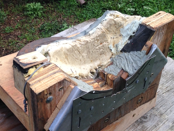
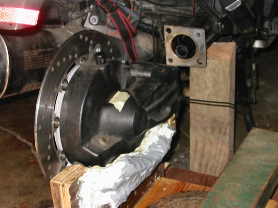
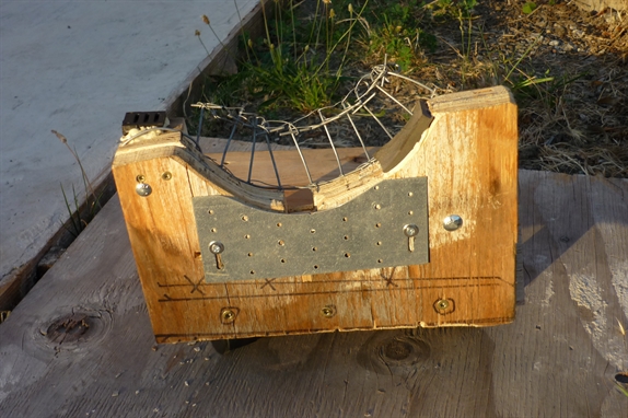
The final drive has a beveled shape with few flat surfaces to use when molding a jig. I did it in many steps. I cut out wood and metal, bending different gauges of wire to match the bevel. I then covered the bent wire with fiberglass cloth and multiple layers of epoxy resin and filler. With great care I avoided contaminating the final drive exterior (or interior) with uncured epoxy.
The sheet metal inner surface of the stand, facing the brake rotor, must be completely flat and smooth, so as not to damage the rotor in motion. Look for a groove at the bottom of the cradle where the final drive drain plug fits undisturbed.
Construction of the tool required a lot of work. A 3D printer might provide a means of reproducing the molded cradle portion of this project. The other parts are not that hard to build and I expect there are riders who could offer improvements.